Short Notes: Network Layer
Inner workings to the Network Layer, the 'IP' of TCP/IP protocol suite.
Internet is a network of networks: computers are connected to each other within networks, and these networks connect to other networks. The “network layer” is the part of the Internet communications process where these connections occur, by sending packets of data back and forth between different networks. The network layer is layer 3. The Internet Protocol (IP) is one of the main protocols used at this layer, along with several other protocols for routing, testing, and encryption.
What Happens at L3 - Packets
Anything that has to do with inter-network connections takes place at the network layer. This includes setting up the routes for data packets to take, checking to see if a server in another network is up and running, and addressing and receiving IP packets from other networks. This last process is perhaps the most important, as the vast majority of Internet traffic is sent over IP.
All data sent over the Internet is broken down into smaller chunks called “packets”. When Bob sends Alice a message, for instance, his message is broken down into smaller pieces and then reassembled on Alice’s computer. A packet has two parts: the header, which contains information about the packet itself, and the body, which is the actual data being sent.
At the network layer, networking software attaches a header to each packet when the packet is sent out over the Internet, and on the other end, networking software can use the header to understand how to handle the packet.
A header contains information about the content, source, and destination of each packet (somewhat like stamping an envelope with a destination and return address). For example, an IP header contains the destination IP address of each packet, the total size of the packet, an indication of whether or not the packet has been fragmented (broken up into still smaller pieces) in transit, and a count of how many networks the packet has traveled through. Some common protocols used in this layer are IP, IPsec, ICMP, IGMP etc.
Network Devices
Devices that interconnect links of the same type are often called switches, or sometimes Layer 2 (L2) switches. A particularly important class of L2 switches in use today are those used to interconnect Ethernet segments. These switches are also sometimes called bridges.
The core job of a switch is to take packets that arrive on an input and forward (or switch) them to the right output so that they will reach their appropriate destination. There are a variety of ways that the switch can determine the “right” output for a packet, which can be broadly categorized as connectionless and connection-oriented approaches.
Given the enormous diversity of network types, we also need a way to interconnect disparate networks and links (i.e., deal with heterogeneity). Devices that perform this task, once called gateways, are now mostly known as routers, or alternatively, Layer 3 (L3) switches.
Once we interconnect the networks, there are likely to be many different possible ways to get from one point to another. Finding a suitable path or route through a network is one of the fundamental problems of networking. Such paths should be efficient, loop free, and able to respond to the fact that networks are not static. Nodes may fail or reboot, links may break, and new nodes or links may be added.
Datagrams
We need to include in every packet enough information to enable any switch to decide how to get it to its destination. That is, every packet contains the complete destination address. To decide how to forward a packet, a switch consults a forwarding table, also called a forwarding table.
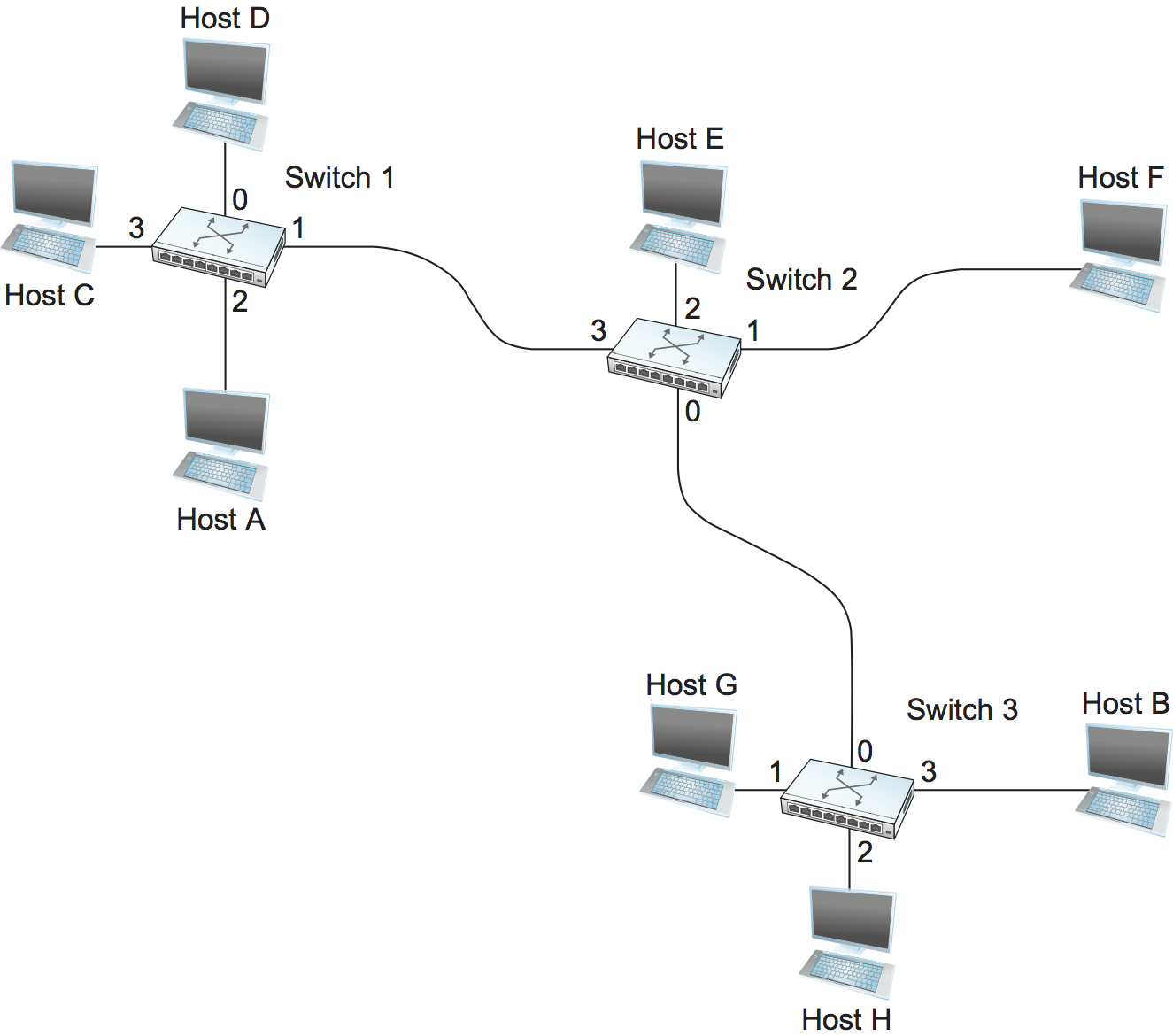
Following would be the Forwarding Table for Switch 2.
| Destination | Portl |
|---|---|
| A | 3 |
| B | 0 |
| C | 3 |
| D | 3 |
| E | 2 |
| F | 1 |
| G | 0 |
| H | 0 |
Each packet is forwarded independently of previous packets that might have been sent to the same destination. Thus, two successive packets from host A to host B may follow completely different paths. A switch or link failure might not have any serious effect on communication if it is possible to find an alternate route around the failure and to update the forwarding table accordingly.
Switching
Switching is a mechanism that allows us to interconnect links to form a larger network. A switch is a multi-input, multi-output device that transfers packets from an input to one or more outputs. We can connect switches to each other and to hosts using point-to-point links, which typically means that we can build networks of large geographic scope.
Every host on a switched network has its own link to the switch, so it may be entirely possible for many hosts to transmit at the full link speed (bandwidth), provided that the switch is designed with enough aggregate capacity. Providing high aggregate throughput is one of the design goals for a switch.
A switch’s primary job is to receive incoming packets on one of its links and to transmit them on some other link. It looks at the header of the packet for an identifier that it uses to make the decision.
L2 v L3 network
Ethernet can be treated as a point-to-point link interconnecting a pair of switches, with a mesh of interconnected switches forming a Switched Ethernet. This configuration is also known as an L2 Network. But ethernet can also be treated as a network interconnecting a pair of routers, with a mesh of such routers forming an Internet. This configuration is also known as an L3 Network.
Confusingly, this is because a point-to-point Ethernet is both a link and a network, depending on whether it’s connected to a pair of L2 switches running the spanning tree algorithm, or to a pair of L3 routers running IP. Why pick one configuration over the other? It partly depends on whether you want the network to be a single broadcast domain (if yes, pick L2), and whether you want the hosts connected to the network to be on different networks (if yes, select L3).
Global Addresses
- Ethernet addresses are globally unique, but that alone does not suffice for an addressing scheme in a large internetwork.
- Ethernet addresses are also flat, which means that they have no structure and provide very few clues to routing protocols.
- Hence we require IP address to move packets across networks.
Internet Protocol
An internetwork is often referred to as a “network of networks” because it is made up of lots of smaller networks. The nodes that interconnect the networks are called routers. They are also sometimes called gateways.
IP service model can be thought of as having two parts: an addressing scheme, which provides a way to identify all hosts in the internetwork, and a datagram model of data delivery. This service model is sometimes called best effort because, although IP makes every effort to deliver datagrams, it makes no guarantees.
Datagram Delivery
- Datagram is a packet sent in a connectionless manner over a network. Every datagram carries enough information to let the network forward the packet to its correct destination.
- The network makes its best effort to get it to the desired destination. The “best-effort” part means that if something goes wrong and the packet gets lost, corrupted, misdelivered, or in any way fails to reach its intended destination, the network does nothing, it made its best effort, and that is all it has to do. It does not make any attempt to recover from the failure. This is sometimes called an unreliable service.
- The ability of IP to “run over anything” is frequently cited as one of its most important characteristics. If you wanted a reliable service model over an unreliable network, you would have to put lots of extra functionality into the routers to make up for the deficiencies of the underlying network. Keeping the routers as simple as possible was one of the original design goals of IP.
Packet Format
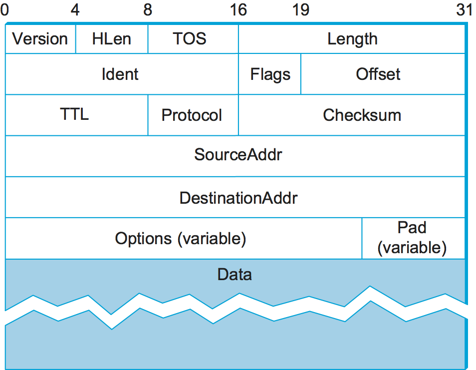
- The
Versionfield specifies the version of IP. The still assumed version of IP is 4, which is typically called IPv4. The header processing software starts off by looking at the version and then branches off to process the rest of the packet according to the appropriate format (IPv4 v IPv6). HLenspecifies the length of the header in 32-bit words. When there are no options, which is most of the time, the header is 5 words (20 bytes) long.- The 8-bit TOS (type of service) field has had a number of different definitions over the years, but its basic function is to allow packets to be treated differently based on application needs.
- The next 16 bits of the header contain the Length of the datagram, including the header. Unlike the HLen field, the Length field counts bytes rather than words. Thus, the maximum size of an IP datagram is 65,535 bytes.
- The physical network over which IP is running, however, may not support such long packets. For this reason, IP supports a fragmentation and reassembly process. The second word of the header contains information about fragmentation.
TTL(time to live) field. The intent of the field is to catch packets that have been going around in routing loops and discard them, rather than let them consume resources indefinitely. One subtlety is in the initial setting of this field by the sending host: Set it too high and packets could circulate rather a lot before getting dropped; set it too low and they may not reach their destination. The value 64 is the current default.- The
Protocolfield is simply a demultiplexing key that identifies the higher-level protocol to which this IP packet should be passed. There are values defined for the TCP (Transmission Control Protocol—6), UDP (User Datagram Protocol—17), and many other protocols that may sit above IP in the protocol graph. - The
Checksumis calculated by considering the entire IP header as a sequence of 16-bit words, adding them up using ones’ complement arithmetic, and taking the ones’ complement of the result. Routers discard any packet that fails the checksum. It should be noted that this type of checksum does not have the same strong error detection properties as a CRC, but it is much easier to calculate in software. - The last two required fields in the header are the
SourceAddrand theDestinationAddrfor the packet. The latter is the key to datagram delivery: Every packet contains a full address for its intended destination so that forwarding decisions can be made at each router. The source address is required to allow recipients to decide if they want to accept the packet and to enable them to reply. - Finally, there may be a number of options at the end of the header. The presence or absence of options may be determined by examining the header length (HLen) field. While options are used fairly rarely, a complete IP implementation must handle them all.
Fragmentation and Reassembly
One of the problems of providing a uniform host-to-host service model over a heterogeneous collection of networks is that each network technology tends to have its own idea of how large a packet can be. This leaves two choices for the IP service model: Make sure that all IP datagrams are small enough to fit inside one packet on any network technology, or provide a means by which packets can be fragmented and reassembled when they are too big to go over a given network technology.
The central idea here is that every network type has a maximum transmission unit (MTU), which is the largest IP datagram that it can carry in a frame. Note that this value is smaller than the largest packet size on that network because the IP datagram needs to fit in the payload of the link-layer frame.
- Fragmentation typically occurs in a router when it receives a datagram that it wants to forward over a network that has an MTU that is smaller than the received datagram. To enable these fragments to be reassembled at the receiving host, they all carry the same identifier in the
Identfield. This identifier is chosen by the sending host and is intended to be unique among all the datagrams that might arrive at the destination from this source over some reasonable time period. - Since all fragments of the original datagram contain this identifier, the reassembling host will be able to recognize those fragments that go together.
- Should all the fragments not arrive at the receiving host, the host gives up on the reassembly process and discards the fragments that did arrive. IP does not attempt to recover from missing fragments.
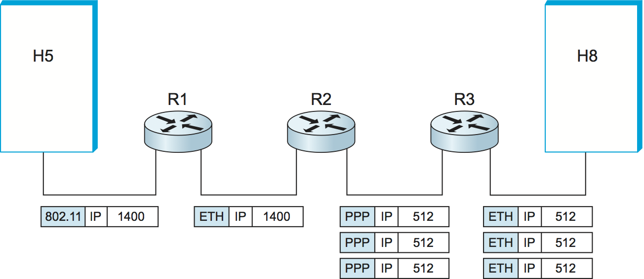
Assuming that the MTU is 1500 bytes, datagram sent from H5 makes it across the network and the first Ethernet without fragmentation but must be fragmented into three datagrams at router R2. These three fragments are then forwarded by router R3 across the second Ethernet to the destination host.
- Each fragment is itself a self-contained IP datagram that is transmitted over a sequence of physical networks, independent of the other fragments.
- Each IP datagram is re-encapsulated for each physical network over which it travels.
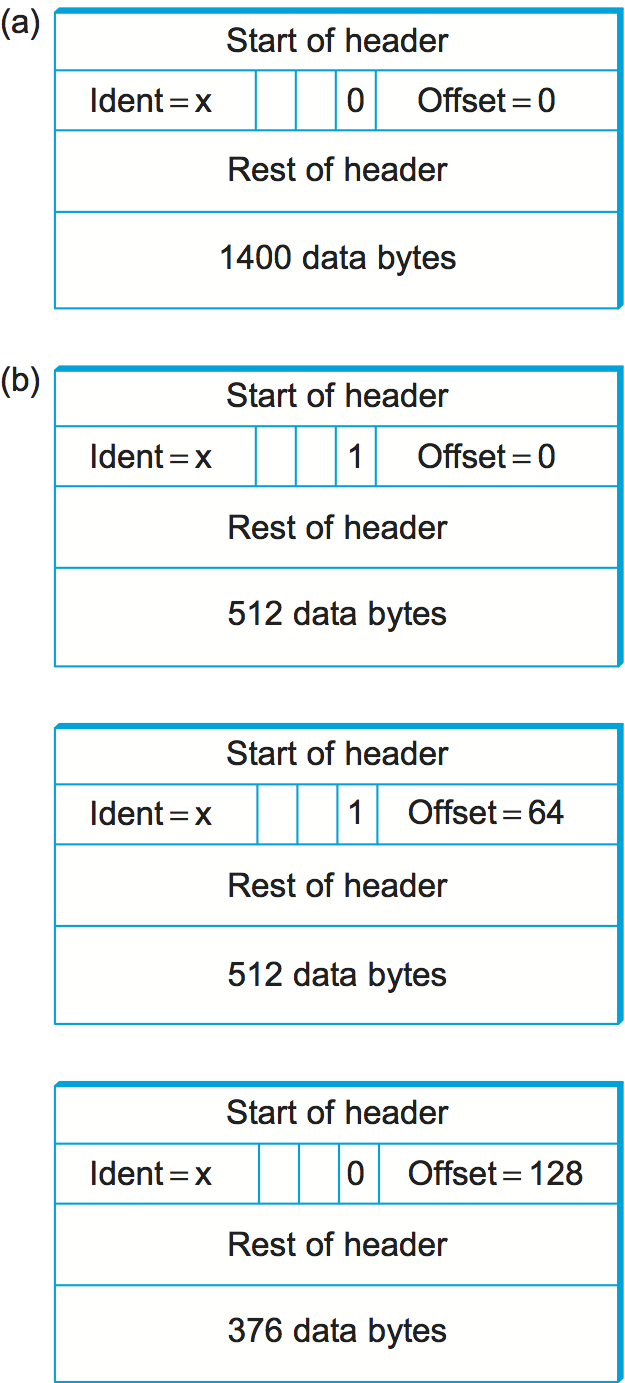
The router sets the M bit in the Flags field, meaning that there are more fragments to follow, and it sets the Offset to 0, since this fragment contains the first part of the original datagram. The data carried in the second fragment starts with the 513th byte of the original data, so the Offset field in this header is set to 64, which is 512/8. Why the division by 8? Because the designers of IP decided that fragmentation should always happen on 8-byte boundaries, which means that the Offset field counts 8-byte chunks, not bytes. The third fragment contains the last 376 bytes of data, and the offset is now 2 × 512/8 = 128. Since this is the last fragment, the M bit is not set.
- Observe that the fragmentation process is done in such a way that it could be repeated if a fragment arrived at another network with an even smaller MTU. Fragmentation produces smaller, valid IP datagrams that can be readily reassembled into the original datagram upon receipt, independent of the order of their arrival. Reassembly is done at the receiving host and not at each router.
IP reassembly is far from a simple process. For example, if a single fragment is lost, the receiver will still attempt to reassemble the datagram, and it will eventually give up and have to garbage-collect the resources that were used to perform the failed reassembly. Getting a host to tie up resources needlessly can be the basis of a denial-of-service attack.
For this reason, among others, IP fragmentation is generally considered a good thing to avoid. Hosts are now strongly encouraged to perform “path MTU discovery”, a process by which fragmentation is avoided by sending packets that are small enough to traverse the link with the smallest MTU in the path from sender to receiver.
Datagram Forwarding in IP
Important things to remember about routing
- Every IP datagram contains the IP address of the destination host.
- The network part of an IP address uniquely identifies a single physical network that is part of the larger Internet.
- All hosts and routers that share the same network part of their address are connected to the same physical network and can thus communicate with each other by sending frames over that network.
- Every physical network that is part of the Internet has at least one router that, by definition, is also connected to at least one other physical network; this router can exchange packets with hosts or routers on either network.
Routing Process
- A Datagram is sent from a source host to a destination host, possibly passing through several routers along the way.
- Any node, whether it is a host or a router, first tries to establish whether it is connected to the same physical network as the destination. To do this, it compares the network part of the destination address with the network part of the address of each of its network interfaces.
- It does so by performing a bitwise AND between its own subnet mask and the destination IP address. If the result equals the subnet number of the sending host, then it knows that the destination host is on the same subnet, that means that the destination lies on the same physical network as the interface, and the packet can be directly delivered over that network.
- If the node is not connected to the same physical network as the destination node, then it needs to send the datagram to a router.
- In general, each node will have a choice of several routers, and so it needs to pick the best one, or at least one that has a reasonable chance of getting the datagram closer to its destination. The router that it chooses is known as the next hop router.
- The router finds the correct next hop by consulting its forwarding table. The forwarding table is conceptually just a list of
(NetworkNum, NextHop)pairs. - Normally, there is also a default router that is used if none of the entries in the table matches the destination’s network number. For a host, it may be quite acceptable to have a default router and nothing else. This means that all datagrams destined for hosts not on the physical network to which the sending host is attached will be sent out through the default router.
Thus, for any network number that Router encounters in a packet, it knows what to do. Either that network is directly connected to it, in which case the packet can be delivered to its destination over that network, or the network is reachable via some next hop router that Router can reach over a network to which it is connected. In either case, Router will use ARP to find the MAC address of the node to which the packet is to be sent next.
Routing via Subnets
- Subnetting can help reducing total number of network numbers that are assigned. The idea is to take a single IP network number and allocate the IP addresses with that network number to several physical networks, which are now referred to as subnets.
- From the PoV of Internet, they will all look like a single network, having only one network number between them. This means that a router will only be able to select one route to reach any of the subnets, so they had better all be in the same general direction.
- The mechanism by which a single network number can be shared among multiple networks involves configuring all the nodes on each subnet with a subnet mask.
- The forwarding table of a router also changes slightly when we introduce subnetting. Previously a forwarding table consisted of entries of the form
(NetworkNum, NextHop).To support subnetting, the table must now hold entries of the form(SubnetNumber, SubnetMask, NextHop). To find the right entry in the table, the router ANDs the packet’s destination address with theSubnetMaskfor each entry in turn; if the result matches theSubnetNumberof the entry, then this is the right entry to use, and it forwards the packet to the next hop router indicated.
An exmaple Forwarding table with subnetting looks like:
| Subnet | Mask | NextHop |
|---|---|---|
| 128.96.34.0 | 255.255.255.128 | Interface 0 |
| 128.96.34.128 | 255.255.255.128 | Interface 1 |
| 128.96.33.0 | 255.255.255.0 | R2 |
| 0.0.0.0 | 0.0.0.0 | R3 |
Not all parts of the internet see exactly the same routing information. This is an example of an aggregation of routing information, which is fundamental to scaling of the routing system.
- CIDR helps us to aggregate routes. That is, it lets us use a single entry in a forwarding table to tell us how to reach a lot of different networks.
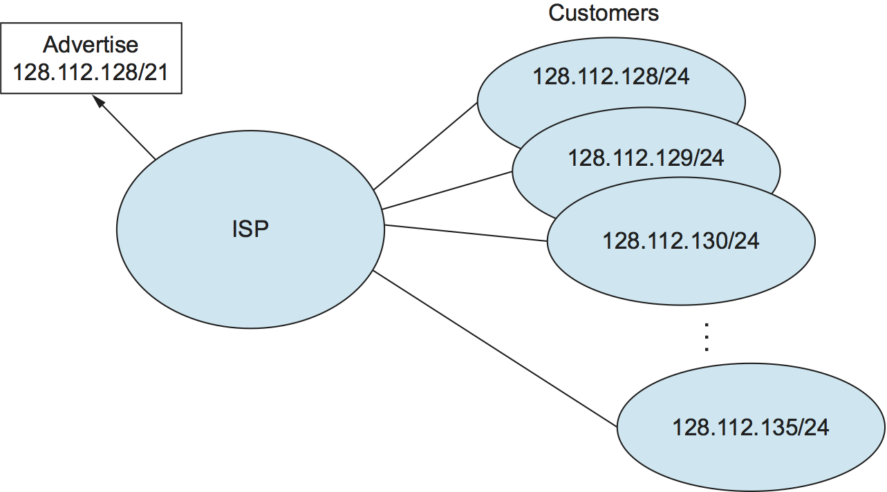
Assume that eight customers served by the provider network have each been assigned adjacent 24-bit network prefixes. Those prefixes all start with the same 21 bits. Since all of the customers are reachable through the same provider network, it can advertise a single route to all of them by just advertising the common 21-bit prefix they share.
IP Forwarding with CIDRs
It is sometimes possible to have prefixes in the forwarding table that “overlap,” in the sense that some addresses may match more than one prefix. For example, we might find both 171.69 (a 16-bit prefix) and 171.69.10 (a 24-bit prefix) in the forwarding table of a single router. In this case, a packet destined to, say, 171.69.10.5 clearly matches both prefixes. The rule in this case is based on the principle of “longest match”; that is, the packet matches the longest prefix, which would be 171.69.10 in this example.
Share this post
Twitter
Facebook
Reddit
LinkedIn
Email